Design Scheme of Combined Ultrafiltration and Reverse Osmosis
发布时间:2026-07-06 分类:Industry News 浏览量:347
1. Core Process Parameters & Design Basis
1.1 Water Flow Basic Parameters
Total inflow capacity: 3000 m³/d, 24-hour continuous operation, hourly inflow rate: 125 m³/h
Target product water capacity: 2000 m³/d industrial reused water, hourly product water rate: 83.33 m³/h
Design recovery rate of UF system: 90% with 1%~2% fluctuation margin. Net UF product water ≥ 2700 m³/d, hourly output 112.5 m³/h to match the feed water load of RO system
Design recovery rate of RO system: 75%. Calculated based on UF product water 112.5 m³/h, theoretical product water reaches 83.33 m³/h with original calculated recovery rate of 74.07%; the whole system is optimized at 75%
1.2 Inflow Control Requirements
Test indicators including COD, turbidity, suspended solids, hardness, TDS, chloride ions of raw water in advance. If raw water turbidity > 10 NTU, add pre-treatment to control UF feed water turbidity ≤ 5 NTU to protect UF membranes.
2. Core Process Flow
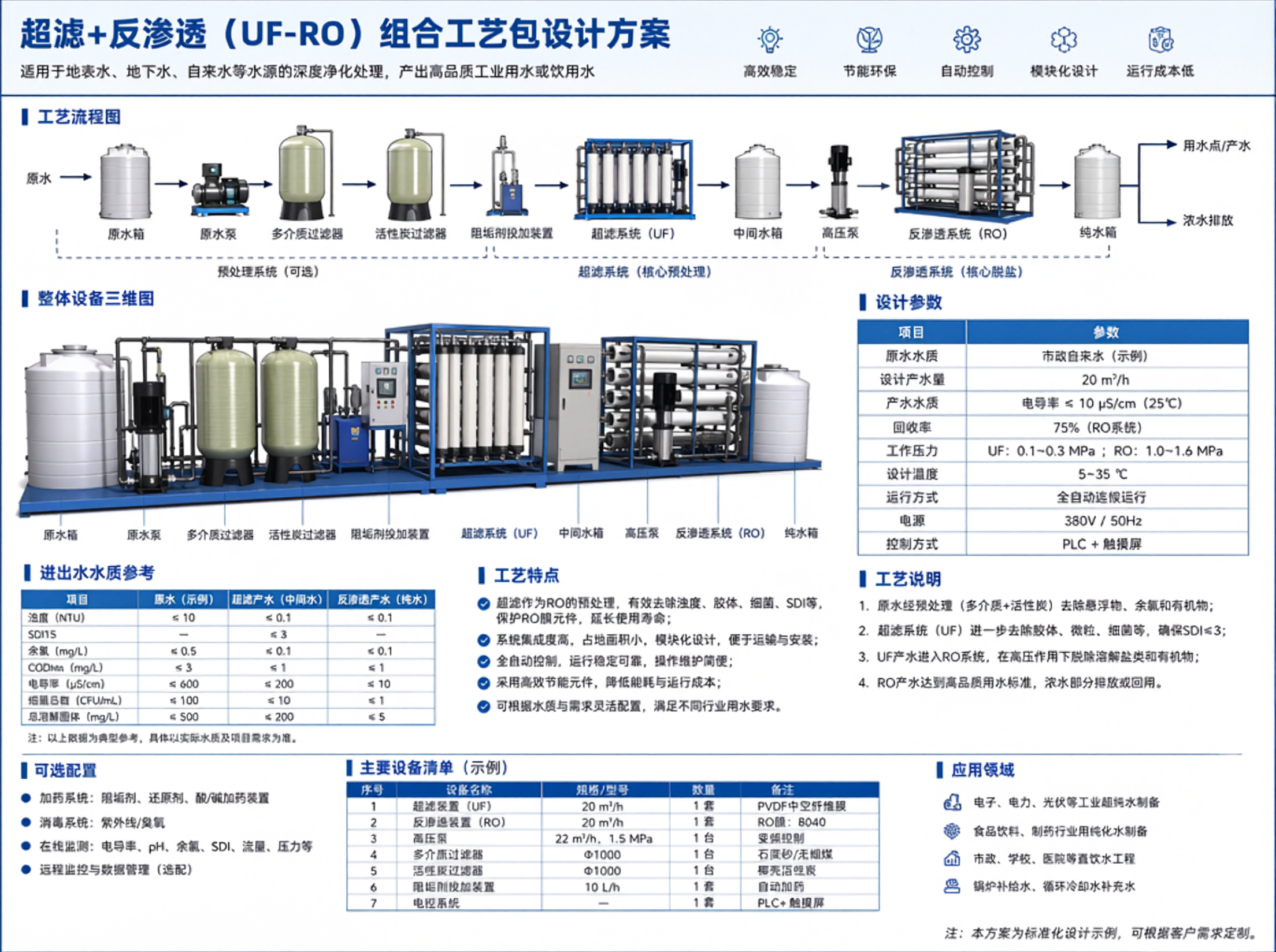
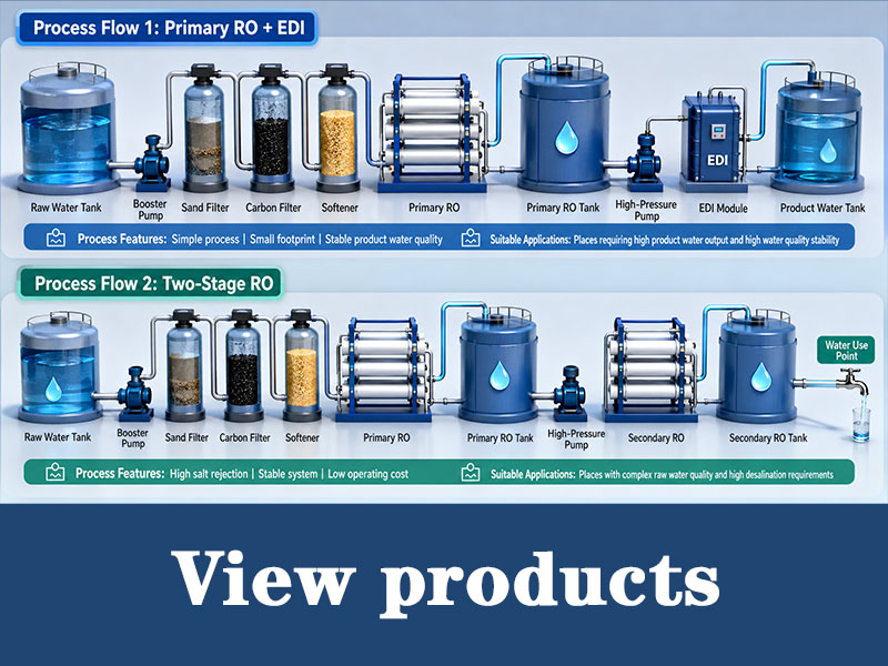
Raw Water → (Optional Pre-treatment: Quartz Sand Filtration + Activated Carbon Filtration) → UF System → UF Product Water Tank → RO Booster Pump → 5μm Cartridge Filter → RO System → RO Product Water Tank → Industrial Reused Water Pipe Network Supporting systems: Chemical Cleaning System, Dosing System, Automatic Control System, Membrane Backwashing System
3. Detailed Design of Each Unit
3.1 Pre-treatment System (Installed as Required)
Applicable scenario: High raw water turbidity, excessive organics/residual chlorine, to prevent UF membrane fouling and RO membrane oxidation & scaling
| Equipment Name | Configuration Specification | Core Function | Operation Control Requirement |
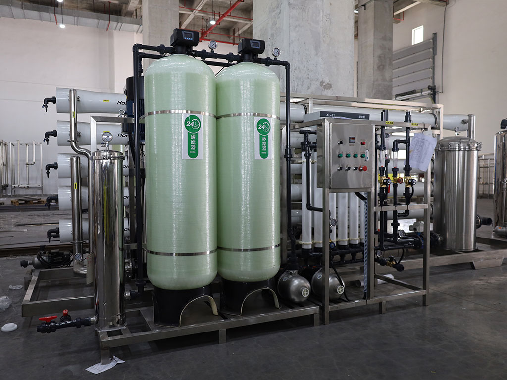
| Quartz Sand Filter | 2 sets (1 working, 1 standby), single capacity 125 m³/h, filter media: 0.5~1.2 mm quartz sand | Remove suspended solids and colloids | Outlet turbidity ≤ 5 NTU |
| Activated Carbon Filter | 2 sets (1 working, 1 standby), single capacity 125 m³/h, coconut shell activated carbon with iodine value ≥ 1000 mg/g | Adsorb residual chlorine and partial organics | Outlet residual chlorine ≤ 0.1 mg/L to avoid membrane oxidation |
3.2 UF Ultrafiltration System
(1) Core Equipment Configuration Table
| Equipment Name | Specification Parameter | Material | Quantity |
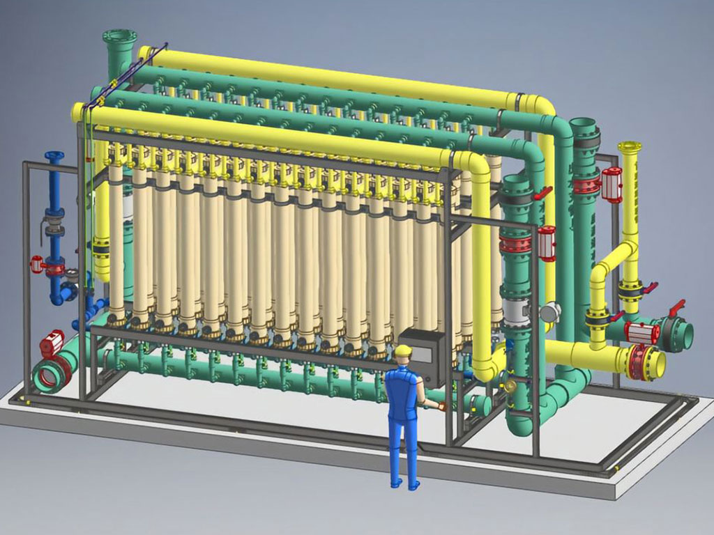
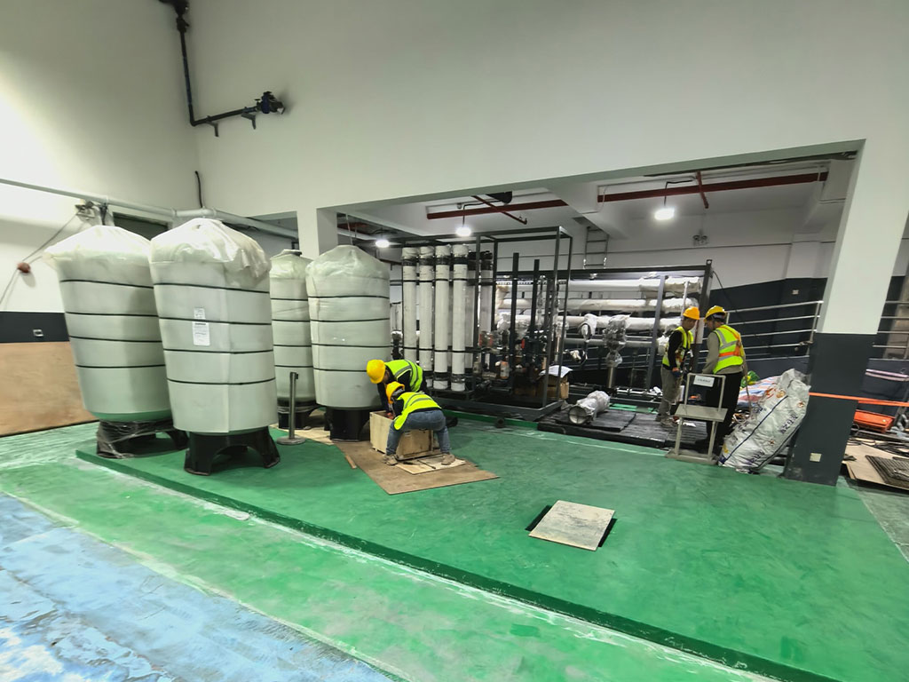
| PVDF External Pressure Hollow Fiber Membrane | Single element production: 5~8 m³/h, single membrane area: 30~40 m² | PVDF | 30 pieces, divided into 3 groups (10 pieces per group) |
| FRP Membrane Housing | Each housing holds 10 membrane elements | FRP | 3 sets |
| UF Feed Pump | Flow rate: 125 m³/h, head: 0.3 MPa | 304 stainless steel | 2 sets (1 working, 1 standby) |
| UF Backwash Pump | Flow rate: 200 m³/h, head: 0.2 MPa | 304 stainless steel | 1 set |
(2) Operation Control Parameter Table
| Item | Control Index | Description |
| System Recovery Rate | 90% | Inflow 125 m³/h, product water 112.5 m³/h, concentrated water 12.5 m³/h; concentrated water can flow back to raw water tank or be discharged externally |
| Operating Flux | 20~25 LMH | Control flux strictly to reduce membrane fouling rate |
| Air Scouring Parameter | Air scouring intensity: 10~15 L/(m²·s) | Operate simultaneously with backwashing |
| Backwashing Regime | Cycle: 30~60 min, single duration: 30~60 s | Automatic intermittent cleaning |
| Chemical Cleaning Trigger Condition | Pressure difference rises by 0.05~0.1 MPa or product water flow drops by 15% | Cleaning cycle: 1~3 months; Acid cleaning: 0.5%~1% citric acid; Alkali cleaning: 0.1%~0.5% NaOH + 0.05% sodium hypochlorite |
3.3 RO Reverse Osmosis System
(1) Core Equipment Configuration Table
| Equipment Name | Specification Parameter | Material | Quantity |
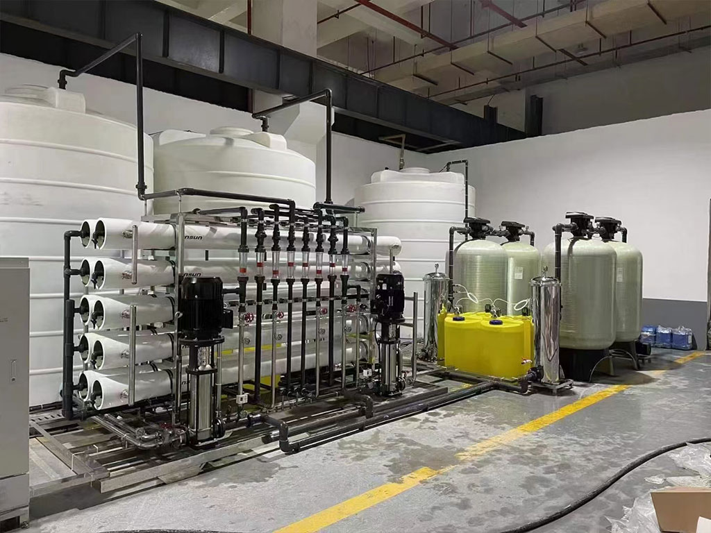
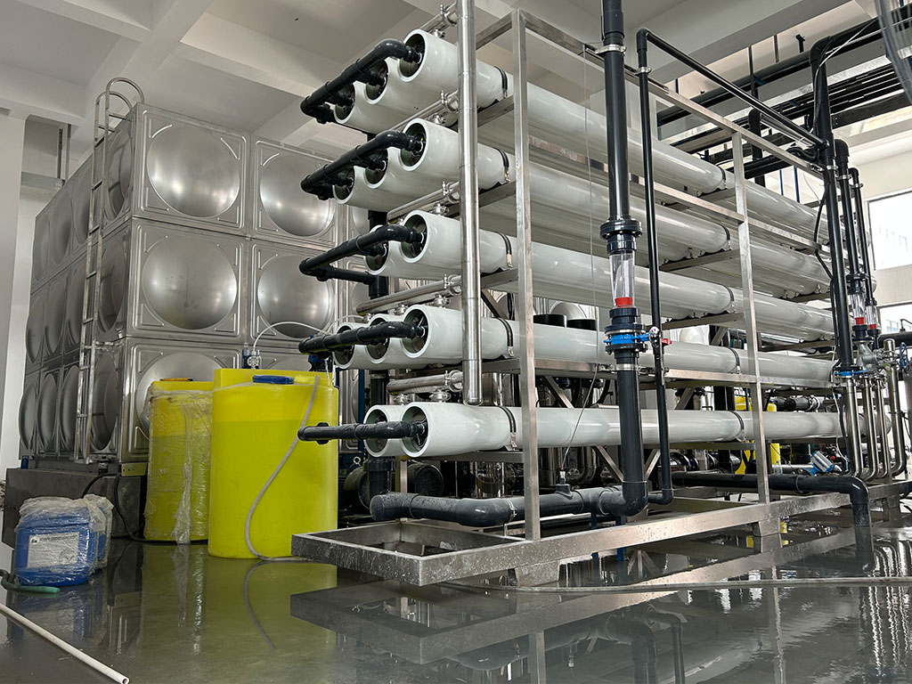
| Low-pressure Composite RO Membrane | Single element salt rejection ≥ 98%, single production: 1.5~2 m³/h, 2:1 arrangement | Aromatic polyamide | 50 pieces, divided into 5 groups (10 pieces per group) |
| RO Membrane Housing | Each housing holds 6~10 membrane elements | FRP | 5 sets |
| RO Booster Pump | Flow rate: 115 m³/h, head: 0.5 MPa | 316 stainless steel | 2 sets (1 working, 1 standby) |
| RO High-pressure Pump | Flow rate: 115 m³/h, head: 1.5~1.8 MPa (adjusted by TDS) | 316 stainless steel | 2 sets (1 working, 1 standby) |
| Cartridge Filter | Capacity: 115 m³/h, filter precision: 5 μm | FRP/stainless steel | 1 set with spare filter cartridges |
(2) Operation Control Parameter Table
| Item | Control Index | Description |
| System Recovery Rate | 75% | RO feed water 112.5 m³/h, product water 84.38 m³/h, concentrated water 28.12 m³/h; concentrated water can be used for greening, toilet flushing or advanced treatment |
| Salt Rejection Rate | ≥ 97% | When raw water TDS = 2000 mg/L, product water TDS ≤ 60 mg/L |
| Scale Inhibition Control | LSI < 0.8 | Dose ATMP scale inhibitor under high hardness raw water condition |
| Chemical Cleaning Trigger Condition | Pressure difference rises by 0.07 MPa, product water drops by 10%, salt rejection decreases by 2% | Cleaning cycle: 3~6 months; Acid cleaning: 1%~2% hydrochloric acid; Alkali cleaning: 0.1%~0.2% NaOH |
3.4 Auxiliary Supporting Systems
(1) Dosing System Configuration Table
| Device Name | Dosing Point | Dosing Parameter | Supporting Equipment |
| Scale Inhibitor Dosing Device | Front of RO cartridge filter | Dosage: 2~5 mg/L (adjusted by water hardness) | Metering pump: 0.1~1 L/h, head: 0.6 MPa |
| Biocide Dosing Device | UF feed end | Sodium hypochlorite dosage: 0.5~1 mg/L, feed residual chlorine ≤ 1 mg/L | Online residual chlorine monitor equipped |
| Membrane Chemical Cleaning Device | Offline cleaning for UF & RO membranes | Circulating acid & alkali cleaning | 500 L chemical tank, cleaning pump: 50 m³/h, head: 0.3 MPa |
(2) Water Tank System Configuration Table
| Tank Name | Volume | Material | Function Description |
| UF Product Water Tank | 50 m³ | 304 stainless steel / FRP | Store 30-min product water to avoid frequent pump start-stop |
| RO Product Water Tank | 80 m³ | 304 stainless steel / FRP | Store 2-hour product water to meet peak water demand; liquid level interlocks unit start-stop |
(3) Automatic Control System
Adopt PLC centralized control with manual/automatic switchover. Automatically execute UF backwashing and high-pressure pump linkage. Real-time monitoring of flow, pressure, turbidity, TDS, residual chlorine and liquid level. Automatic alarm for abnormal pressure difference and liquid level, equipped with touch screen HMI to reduce manual operation.
4. Process Performance Guarantee & Optimization Scheme
Total system recovery rate = RO product water / raw water inflow ≈ 66.7%, within the economic range of 60%~70% for industrial reuse. Excessively high recovery rate will aggravate membrane fouling and is not recommended. To improve recovery rate, recycle RO concentrated water to UF feed end (continuous water quality monitoring required to avoid pollutant accumulation), total recovery rate can reach 70%~75%.
Membrane Fouling Prevention & Control
UF Membrane: Reduce inlet turbidity via pre-treatment, regular air-water combined backwashing, periodic chemical cleaning; design service life: 3~5 years
RO Membrane: Control feed residual chlorine ≤ 0.1 mg/L to prevent oxidation, continuous scale inhibitor dosing, regular chemical cleaning; design service life: 2~3 years
Energy Consumption Optimization
Low energy consumption for UF unit: 0.2~0.3 kWh/m³ product water
RO high-pressure pump is the main energy consumer: 1.0~1.5 kWh/m³ product water. Variable frequency high-pressure pump can automatically adjust frequency according to feed pressure, saving 10%~15% power consumption.
5. System Acceptance Standards
Water Volume Index: Continuous stable operation for 72 hours, daily net UF product water ≥ 2700 m³, daily RO product water ≥ 2000 m³, total system recovery rate ≥ 66.7%
Operation Stability: Equipment failure-free operation rate ≥ 95%; under stable working condition, UF membrane pressure difference ≤ 0.15 MPa, RO membrane pressure difference ≤ 0.2 MPa, all operating parameters meet design requirements.